Natural Gas and LNG Technology
Origins and Properties of Natural Gas
Natural gas is formed from plankton, water-dwelling micro-organisms that include algae and protozoa. As these micro-organisms died and accumulated on the ocean floors, they were slowly buried and their remains were compressed under layers of sediment. Over millions of years, the pressure and heat exerted by the overlying sediments chemically transformed this organic material into natural gas.
Natural gas is a mixture of various gases, the main ingredient being methane CH4. Methane (C1) is colorless at ambient temperature, odorless, non-toxic but a serious “greenhouse gas”.
Natural gas is almost always considered a non-renewable energy source. However there are some renewable sources of methane in the form of landfill sites from which the gas can be recovered.
Because oil and natural gas are formed by similar natural processes, the two are often found together in underground reservoirs. After gradually forming in the Earth’s crust, oil and natural gas slowly flow into tiny holes of nearby porous rocks that serve as eventual reservoirs.
Because this porous reservoir rock is often filled with water, the oil and natural gas, both of which are lighter than water and less dense than the surrounding rock, migrate upwards through the crust, sometimes for long distances. Eventually, some of these upward-moving hydrocarbons become trapped by an impermeable (nonporous) layer of rock, known as the cap rock. Natural gas is lighter than oil, so it forms a layer over the
oil. This layer is called a gas cap.
Natural gas has been discovered on all continents except Antarctica. World natural gas proven reserves, at the end of 2003 total approximately 176 Tcm (trillion cubic meters). The world’s largest natural gas reserves, totaling 72 Tcm are located in the Middle East. The second largest reserves, 62 Tcm are found in Europe and Eurasia with 47 Tcm of those reserves located in the Russian Federation. Vast deposits are also located in other parts of world with Asia Pacific totaling 13.5 Tcm, Africa 13.8 Tcm, South & Central America 7.2 Tcm, United State total 5.5Tcm and
Canada 1.66 Tcm.
Natural gas can be recovered from three different sources:
• On and offshore hydrocarbon reservoirs, which are mainly gas bearing – non associated gas.
• Condensate reservoirs – natural gas liquids (NGL).
• Oil producing reservoirs – associated gas.
Associated gas may be found either in solution with crude oil or as a gas cap.
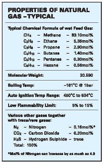
Natural hydrocarbon reservoir (feed) gas, whether associated (with crude) or not varies enormously in its properties and requires chemical processing to remove undesirable components such as nitrogen, carbon dioxide, hydrogen sulfide and water and contaminants such as mercury to obtain saleable products such as sales/LNG feed gas, liquid petroleum gas (LPG) and condensates.
A simple gas process scheme will remove slugs (hydrocarbon liquids) and solids remove acid gas and desulfurize or sweeten to remove sulfur compounds and dehydrate the wet gas. Because the downstream natural gas liquids (NGL) separation operates at cryogenic temperatures, total removal of water is necessary to prevent equipment from freezing.
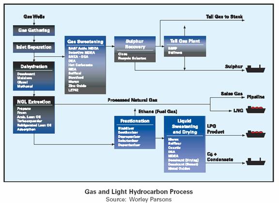
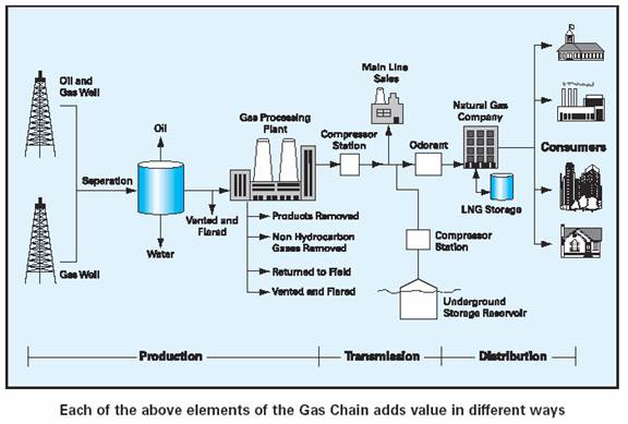
After mercury removal, the dry and mercury free natural gas is processed by cryogenic extraction for recovery of NGL’s. The recovered NGL’s are further processed into LPG and natural gasoline fractions (condensate) which may need additional treatment to remove sulfur compounds. The residue gas from cryogenic extraction process is then compressed and sold either as sales (pipeline) gas (av 85mol% methane C1) or feed gas for LNG production. The diagram below describes simplistically the gas and light hydrocarbon process and examples of technologies involved.
Most natural gas liquids are processed to separate the heavier hydrocarbon liquids from the natural gas CH4 [(C1) methane]. These heavier hydrocarbon Liquids, or NGL’s, traditionally have a higher value than the gaseous natural gas chain. Principal NGL’s include ethane (C2), LPG’s such as propane (C3), butanes (C4) and natural gasoline or plant condensate.
The separation or extraction of NGL’s, as described simplistically below, from the natural gas stream is performed to enhance the ultimate value of the raw natural gas stream. The properties of NGL’s can consist of the following components:
• Ethane C2H6(C2) – Often use as fuel gas for processing, or added to the pure methane sales of LNG feedstock gas to improve burning characteristics or as
feedstock in a stream cracker to make ethylene.
• Propane C3H8(C3) – LPG marketed as propane (preferred fuel intemperate climates) or mixed with butane as mixed LPG.
• Butanes C4H10(C4) – LPG marketed as butanes (i/n) preferred fuel in tropical climates or mixed with propane as mixed LPG or gasoline blending or petrochemical feedstock.
• Pentanes C5H12(C5) and heavier – Represents only 0.8%mol of NGL and not normally separated from plant condensate.
• Natural Gasoline (plant condensate) – Does not contain middle distillates and heavier components of field condensate. Marketed as light naphtha and traded as feedstock for olefins stream crackers. Worldwide natural gasoline production is 1.1 million bcd.
• Field Condensate – Heavier and comes from free gas (not associated) and resembles crude oil in some respect with a density of °API 43 -72. Traded as a light substitute for crude oil, lighter and paraffinic condensate is used as steam cracker feedstock or as an addition or an alternative to refinery naphthas and gasoils. Worldwide field condensate production is 2.5 Mbcd.
If the heavier hydrocarbon liquids are left in the gas, they are valued as part of the gas sale price, instead of the much higher premium paid as individual LPG’s or condensates.
• The last 15 years has seen world demand for liquefied petroleum gas (LPG) outpace total petroleum demand. Purvin & Gertz estimates that total LPG demand growth will average over 3.5% per year, while total petroleum demand over the same period will grow approximately 1.7% per year.
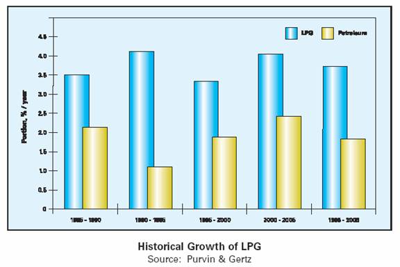
In 1985 the total world LPG demand was approximately 116 million tonnes with estimates for 2005 at nearly 240 million tonnes, 35% of that demand being East of Suez and worth in terms of global turnover $100 billion.
This example of the gas value chain begins with the natural gas resources and ends with the ultimate shareholder/buyer and in this instance it is The National Gas Company of Trinidad and Tobago Limited (NGC). In the ground, natural gas is of no value and only becomes a valued natural resource once it has been extracted and turned by chemical processing from a raw product into a usable commodity and its products sold to the market.
Primary responsibility for spanning the chain, planning and market development activities, seeks to guide and shape the industrial development in such a way that maximum value of the resource is derived for the country, which in this case is Trinidad and Tobago, is vested in NGC.
The first visible activity in the gas chain is exploration and production.
In this example, most of the natural gas is produced from offshore fields leased to foreign companies. At the second link of the chain, the processed gas, from which natural gas liquids (NGL) has already been extracted is purchased and transported to the various commercial and domestics markets by NGC. This purchase, transportation and sale of the natural gas to a variety of consumers, start the process of making it a valued resource. These consumers convert the gas into valued products when used as feedstock in the production of petrochemicals or as fuel for industry and power generation.
The major usage, in addition to supplying all the countries electrical needs, is the production of ammonia, methanol, heavy industrials such as iron and steel, cement and hydrocarbon refining.
The value of natural gas has two dimensions:
• The economic activity that it generates such as employment, industrial, technology and infrastructure developments.
• Revenues in the form of royalties, foreign exchange earnings, personnel and corporate taxes and dividends from investments.
These provide the state amenities and facilities that benefit the citizens of Trinidad and Tobago, securing the future for generations to come. This is a prime example of how value is added to the gas chain.
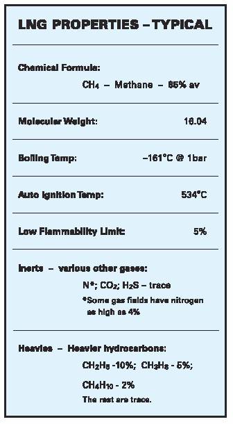
Liquefied Natural Gas (LNG) is exactly what the name implies: natural gas processed to a liquid state. The production of LNG involves a refrigeration procedure that condenses natural gas to a liquid by passing it through a series of refrigeration steps that reduce the temperature to approximately –161°C (-260°) at atmospheric pressure and then stored as a boiling liquid. This liquefaction reduces the volume of natural gas by approximately 600 times making it economical to ship around the world. The ‘inerts and heavies’ condense at various temperatures throughout this process and are removed. The result is 85%-95% pure methane (C1) in liquid form. The tabulation below lists the chemical properties of typical LNG. Actual chemical properties of contracted LNG in terms of mol% can vary only in terms of methane, ethane and nitrogen content.
LNG is odorless, colorless, noncorrosive, non-toxic, lighter than air when vaporized and water when liquid. However, as with any gaseous material except air and oxygen, the natural gas vaporized from LNG can asphyxiate in unventilated areas.
Properties of LNG can change and be variable as the emergence of a more fluid LNG market and growing demand for “lean LNG” (low calorific value), especially in the US and UK and “rich LNG (high calorific value) in Japan, are forcing LNG producers to address new gas quality issues. Changes in calorific values as defined in the Wobbe Index as million Joules/cu m is achieved by either the introduction of additional nitrogen (lean) or LPG (rich).
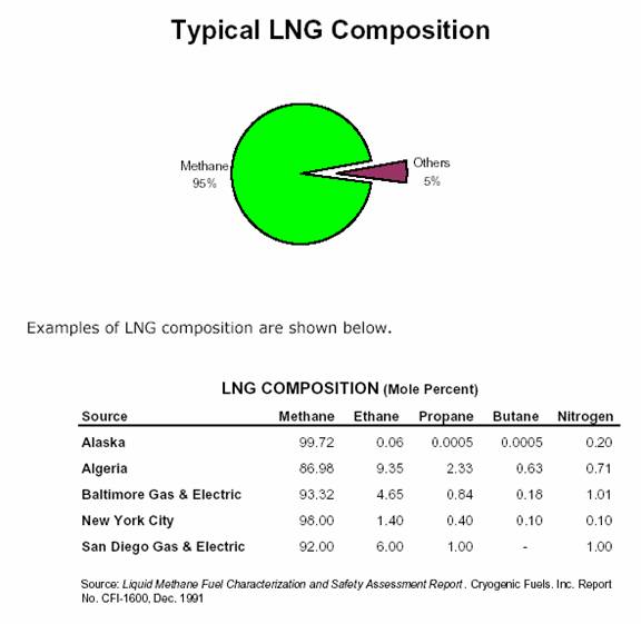
Most LNG consists of av 85mol% methane, a few percent of ethane and less than 1mol% nitrogen; (although some critical fields like the North Field/South Pars field in Qatar/Iran has 4mol% nitrogen).
It is produced by liquefying methane at atmospheric pressure to a temperature of –161°C (-260°F).
The LNG chain starts as the first link in the gas reservoirs on one side of the world with the last link being the end users on the other side of the world.
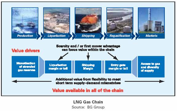
The major links being:
• Exploration and production of natural gas as feed gas for liquefaction.
• Liquefaction, which consists of chilling natural gas to a temperature of –161°C at atmospheric pressure. LNG is roughly 1/600th the volume of natural gas, for an equal quantity of energy.
• Shipping over long distances on board LNG carriers, dedicated vessels in which the liquefied gas is maintained at a temperature of –161°C at atmospheric pressure.
• Regasification, which takes place once the LNG reaches its destination. The liquid is heated in receiving terminals close to consumer markets to convert it back to its initial gaseous form.
• Market demands are met by transmission and distributed by pipeline of the natural gas to end users or pumped to storage in caverns (such as salt domes), pressured to 2000psi and warmed to vapor at 40C.
Feed gas to the liquefaction plant is transported as raw natural gas by pipeline from the production fields and then processed to remove liquid condensate, water (dehydration), acid (CO2, H2S and other sulfur containing compounds) and other contaminates such as mercury to avoid freezing up and damaging equipment. The now dry and sweet feed gas is cooled to becoming a liquid at around –161°C at atmospheric pressure.
It is stored at ambient pressure in a purpose built double or full containment tank until loaded on a double hull LNG tanker. These double walled storage tanks are in fact a tank within a tank, the inner tank being made of materials suitable for cryogenic service and structure loading of LNG. These materials include 9% nickel steel and aluminum. The outer tank is a prestressed concrete wall for containment and for physical protection. The receiving terminal has an identical LNG storage tank.
The basic liquefaction process cools (compressed gas released through a valve creates the Joules-Thompson effect [JT ]), the dry, sweet feed gas in successively colder heat exchangers that use propane, ethylene and methane as refrigerants. The product leaving the methane exchangers is liquid and is ready for pumping into insulated storage tanks. Gases continually boil out of the LNG as it warms slightly in the storage tank and these are captured and returned to the process for reliquefying. Approximately 10% of the feed gas received by a liquefaction plan is consumed by its own operations.
The produced LNG is roughly 1/600th the volume of natural gas for an equal quantity of energy, enabling it to be transported by cryogenic tankers to energy hungry markets where it is regasified and fed as natural gas to the transmission grid. This is equivalent to a 17 inch beach ball being reduced to the size of a ping-pong ball!
LNG has to meet stringent commercial specifications that vary depending on the market destination. These specifications including heating values and Wobbe index which characterizes the combustion (richness of the methane) properties of the delivered gas. Richness for the Japanese is achieved by the introduction of a small percentage of process NGL or leanness for the US and UK markets by nitrogen injection.
The refrigeration and liquefaction section is the key element of the LNG plant. There are several different licensed processes, detailed below, available with varying degrees of application and experience.
The basic principles for cooling and liquefying the feed gas using the refrigerant involve matching as closely as possible the cooling/ heating curves of the process gas and the refrigerant. This results in a more efficient thermodynamic process requiring less power per unit of LNG produced. This applies to all liquefaction processes. The way this is achieved and the equipment used, plays a major part in the overall efficiency, operability, reliability and cost of the plant. This liquefaction section typically accounts for 30% to 40% capital costs of the overall liquefaction plant which in turns accounts for 25% to 35% of total project costs.
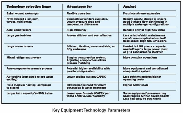
Detailed in the table above are some key equipment technology parameters used in all processes to circulate and cool the refrigerants.
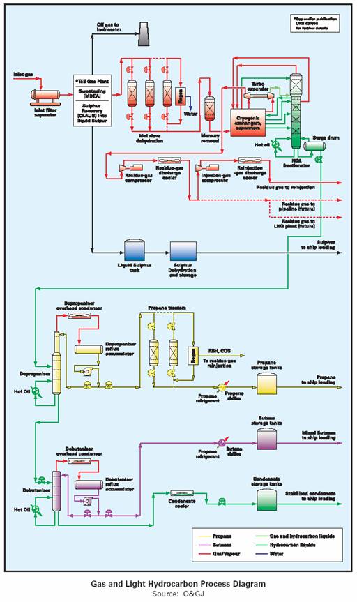
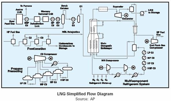
Most of these components are easy identifiable on the LNG process flow diagrams shown below.
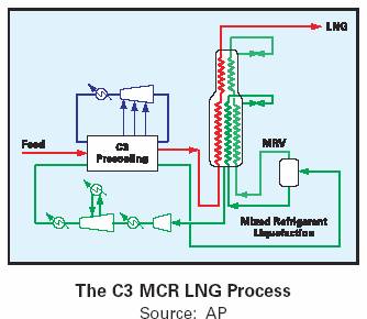
Although the liquefaction process developed by Air Products is used by more than 85% of all LNG plants, there are now a number of alternative technologies to choose from including the AP C3 MCR for large capacity trains. Each technology detailed below is in use in current LNG plants or is being proposed or applied in new or planned LNG projects.
Air Products – Propane Pre-Cooled Mixed Refrigerant (C3 MCR) Process–Train capacity of up to 4.7 Mtpa. This process uses a propane (C3) precooled gas stream that expands through a JT valve at the main heat exchanger for immediate condensation. A cascade MCR (Multi Component Refrigerant) refrigeration system is used for cryogenic cooling.
The above diagram shows the full refrigeration and liquefaction processes as a simple flow diagram.
The diagram above shows a simple LNG plant using the AP–C3 MCR process and the processes to remove undesirable components and contaminants before liquefaction.
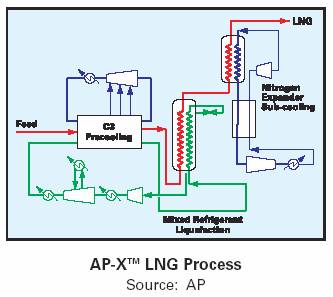
Air Products – AP-Xtm Process for large capacity plants – Train capacities of up to 8.0 Mtpa are planned. AP-Xtm offer capital savings of over 10% for one train compared to 2 x 50% C3 MCR trains.

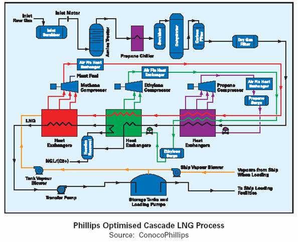
ConocoPhillips - Optimized Pure Refrigerant Cascade LNG
Process – Train capacities of up to 3.3 Mtpa have been built with a 5.4 Mtpa train in development. The original cascade process consisted of three chilling cycles using different refrigerants – propane C3, ethylene C2 and methane C1. Each refrigerant has a sequentially lower boiling point, e.g. C3 (–33°C), C2 (–90°C), C1 (–150°C). The sub-cooled liquid (–150°C) is flashed to reduce temperature further to (–161°C).
• Shell Global Solutions - Dual Mixed Refrigerant (DMR) Process
Train capacities of up to 2 x 4.8 Mtpa trains for operation in arctic climates, such as Sakhalin LNG plants.
• Statoil-Linde Mixed Fluid Cascade (MFC) Process
Train capacity of up to 4 Mtpa under construction.
• Axens/IFP – ‘Liquefin’ DMR Process
Based load train capacity of up to 6 Mtpa is under consideration for Iran.
• SMR – Black & Veatch PRICO®
Single mixed refrigerant process used originally on a base load plant in Algeria and now used on similar base load and peak shaver plants.
A chart detailing worldwide base load LNG capacity based on liquefaction technologies as of December 2003 is listed below.

Better-designed equipment, coupled with bigger liquefaction trains, has produced significant productivity gains, but the increasingly contentious issue of CO2 emissions is imposing restrictions on the use of larger gas turbines to power the refrigerant compressors.
As a result, there is a growing trend to use combined cycle power plants to power liquefaction compressors with electric drivers instead of gas turbines thus reducing gas consumption by liquefaction facilities. Other avenues for progress include optimizing auxiliary installations such as steam generators, seawater pumps, storage tanks and loading equipment.
Future development of floating liquefaction, storage and regasification facilities will greatly expand the scope for use of LNG facilities, especially in the production and transportation of gas from remote locations. These solutions either take us closer to offshore fields or eliminate various obstacles that limit the number of available sites for liquefaction plants and terminals.
In a more open and flexible market, some operations to tailor LNG quality, such as lean LNG, in order to better satisfy specific local requirements, could be transferred to regasification terminals. At present, only a few terminals reprocess gas, either reducing Btu content through nitrogen injection to comply with American/UK standards or increasing it with propane and butane to satisfy Japanese gas distributors.
With the development of longer supply routes, shipping accounts for an increasing share of LNG industry capital expenditure and operating costs. Controlling transportation creates “added value”, since companies can redirect ships to take advantage of regional price differences through arbitrage transactions, which are growing rapidly and know as “LNG Swapping”.
However, the spread of LNG remains dependent on maintaining an excellent shipping safety record, complying with very stringent standards concerning shipbuilding, crew qualifications and application of strict maintenance procedures to these very complex ships. With the exceptions of shipyards where the ships were built, there are few shipyards worldwide that have wet and dry docks and shore side facilities that can provide the required level of marine services, systems maintenance together with the associated safety and environmental standards.
LNG tankers are double-hull ships specially designed and insulated to prevent leakage or rupture in an accident. The LNG is stored in a special containment system within
the inner hull where it is stored at atmospheric pressure and at –160°C.
Three types of cargo containment systems have evolved as modern standards. These being:
• The “Moss” tankers feature spherical self-supporting cargo containment systems. These tanks are made of thick aluminum plates, welded and insulated.
They are anchored to the ship’s double hull using a steel skirt with a thermal brake made from a special alloy.
• The Membrane tankers use a technology developed by Gaz Transport & Technigaz. The LNG is contained by a thin double metal barrier, or membrane, that creates liquid-tight containment barriers and maintains its mechanical properties at low temperature.
Loads are transferred to the double hull by the insulation, which protects it from the cold.
The tank shape is designed to make optimal use of the available space on the vessel.
• The structural prismatic concept.

The figure above shows that currently most of the LNG ships use spherical (Moss) tanks, and they are easily identifiable as LNG ships because the top half of the tanks are visible above the deck. Most of the new LNG ships are using the membrane design.

The typical LNG carrier currently being built can transport about 135,000 – 145,000 m3 of LNG, which will provide about 2.8 – 3.0 billion Bcf of natural gas. The typical carrier measures some 900 feet in length, about 140 feet in width and 36 feet in water draft, and costs about $160 million. A few of the LNG tankers recently ordered are as large as 205,000 cubic meters. LNG tankers are generally less polluting than other shipping vessels because they can burn natural gas in addition to fuel oil as a fuel source for propulsion.
LNG Storage and Regasification
LNG onshore receiving terminals (anywhere between 2 Mtpa and 12 Mtpa) consist of offloading installations, cryogenic storage tanks (between 40,000m3 to 180,000m3), pumps and regasification facilities.
The LNG is warmed from –161°C to just above 0°C at a pressure of between 60 and 100 bar, usually using seawater percolation heat exchangers, a technique that is highly energy efficient when the water quality is suitable. The LNG can also be heated by burning some of the produced gas.
In some terminals, co-generation is used to produce heat and power, thereby enhancing energy efficiency.
When the gas leaves the terminal, its heating value is adjusted, where applicable, by modifying the nitrogen, butane or propane content or by blending with other gases before being fed into the distribution grid, piped directly to major gas users such as power stations or sent to long or short term storage facilities such as on and offshore salt caverns. Examples of which are shown later on.
LNG tanks are a large portion of the cost for a new onshore receiving terminal and advances in technology, materials and construction techniques have pushed up sizes upward from 40,000/98,000m3 10 years ago to180,000m3 today.
Costs for single containment LNG tanks has actually dropped in the last 10 years. Today the price for a 130,000m3 single containment tank is now around $27 million, compared to $55 million in the early 1990’s for a 110,000m3 one. Full containment tanks are more expensive costing $55 – $75 million for the larger 160,000m3 class. The diagrams below details the primary cost variables for types of storage tanks.

A 120,000m3 double wall LNG storage tank with a diameter of 75 meters and height of 46 meters and insulation thickness of 1,000mm, Inner shell is 9% nickel steel.

A 120,000m3 double wall full containment LNG storage tank with a diameter of 75 meters and height of 46 meters and insulation thickness of 1,000mm, Inner shell is 9% nickel steel.

An onshore terminal site has to meet a variety of criteria that include safety and availability of access to the sea, proximity of distribution grids and consumer areas, and sufficient space to maintain an adequate safety distance from inhabited areas and other human activities.
A marine loading/unloading terminal after the cost of the LNG storage tank is the next most expensive item with a long approach (trestle) costing $150 million plus an additional $80 million for a breakwater.
The terminal also has to respect the natural environment and be accepted by neighbors in terms of its impact on local activities and the landscape. Since fewer and fewer sites offer this combination, operators are developing new concepts to meet all the requirements.
They are also considering offshore installations, which may prove to be the only appropriate solution in some cases.