A Descriptive Definition of Valve Actuators
By Chris Warnett, Rotork Controls Inc
A valve actuator is any device that utilizes a
source of power to operate a valve. This source of power can be a human being
working a manual gearbox to open or close a valve, or it can be a smart
electronic device with sophisticated control and measuring devices. With the
advent of micro-circuitry the trend has been for actuators to become more
sophisticated. Early valve actuators were no more than a geared motor with
position sensing switches. Today’s valve actuators have much more advanced
capabilities. They not only act as devices for opening and closing valves, but
can also check on the health and well being of a valve as well as provide
predictive maintenance data.
What is an actuator?
An actuator in its broadest definition is a device that produces linear or
rotary motion from a source of power under the action of a source of control.
Actuators take fluid, electric or some other source of power and convert it
through a motor, piston or other device to perform work. Basic actuators are
used to move valves to either fully opened or fully closed positions. Actuators
for control or position regulating valves are given a positioning signal to move
to any intermediate position with a high degree of accuracy. Although the most
common and important use of an actuator is to open and close valves, current
actuator designs go far beyond the basic open and close function. The valve
actuator can be packaged together with position sensing equipment, torque
sensing, motor protection, logic control, digital communication capacity and
even PID control all in a compact environmentally protected enclosure.
Figure 1: Basic electric actuator components
As automation is adopted in more facilities, physical work is being replaced
by machines and their automatic controls. The need for valve actuators to
provide the interface between the control intelligence and the physical movement
of a valve has grown. There is an important need for the increased working
safety and the environmental protection that valve actuators can provide. Some
areas are hazardous or hostile to human beings. In these circumstances an
automated actuation device can reduce the risk to the individuals. Certain
critical valves need to be opened or closed rapidly in the event of emergency
circumstances. The valve actuator can prevent serious environmental catastrophes
as well as minimize damage to facilities in such circumstances. With some
processes requiring high pressures and large line sizes, the amount of power
required to open or close a valve can be significant. In these circumstances the
enhanced mechanical advantage and application of high output motors can
facilitate easy operation of large valves.
Valves and automation
In order to successfully automate a process it is essential to make sure that
the valve itself is appropriate to handle the special demands of the process and
the product in the pipeline. It is the process or product that should dictate
the type of the valve, the closure element of the valve, trim requirements and
material of construction.
Once a valve has been selected the next step is to consider the application’s
automation requirements. These can be simplified by examining the two basic
types of valve operation from an actuator’s perspective.
- Rotary or quarter-turn operation. This group would include plug valves,
ball valves, butterfly valves as well as quarter-turn dampers. A simple 90° of
movement at the prescribed torque demand is required.
- The other group of valves can be classified as multi-turn. These are
valves that have rising non-rotating stems or non-rising rotating stems. In
other words they require multiple turns to move the valve closure element from
open to close. This group would include globe valves, gate valves, knife
gates, sluice gates, etc. Alternatively, linear, pneumatic or hydraulic piston
operators or diaphragm pneumatic actuators could be used.
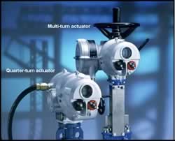
Figure 2: Multi turn & quarter turn actuators
There are four fundamental types of actuators. These are a combination of the
type of power applied and the type of movement required at the valve.
- Electric multi-turn actuators –The electrically powered multi-turn
actuators are one of the most common and dependable configurations of
actuators. A single or three-phased electric motor drives a combination of
spurs and/or level gears, which in turn drive a stem nut. The stem nut engages
the stem of the valve to open or close it, frequently via an Acme threaded
shaft. Electric multi-turn actuators are capable of quickly operating very
large valves. To protect the valve, the limit switch turns off the motor at
the ends of travel. The torque sensing mechanism of the actuator switches off
the electric motor when a safe torque level is exceeded. Position indicating
switches are utilized to indicate the open and closed position of the valve.
Typically a declutching mechanism and hand wheel are included so that the
valve can be operated manually should a power failure occur. The main
advantage of this type of actuator is that all of the accessories are
incorporated in the package and are physically and environmentally protected.
It has all the basic and advance functions incorporated in a compact housing
which can be water tight, explosion proof and in some circumstances,
submersible. The primary disadvantage of an electric multi-turn actuator is
that, should a power failure occur, the valve remains in the last position and
the fail-safe position cannot be obtained easily unless there is a convenient
source of stored electrical energy.
- Electric quarter-turn actuators –These units are very similar to an
electric multi-turn actuator. The main difference is that the final drive
element is usually in one quadrant that puts out a 90° motion. The newer
generation of quarter-turn actuators incorporates many of the features found
in most sophisticated multi-turn actuators. For example, a non-intrusive,
infrared, human machine interface for set up, diagnostics, etc. Quarter-turn
electric actuators are compact and can be used on smaller valves. They are
typically rated to around 1,500 foot pounds. An added advantage of a smaller
quarter-turn actuators is that, because of their lower power requirements,
they can be fitted with an emergency power source such as a battery to provide
failsafe operation.
- Fluid power quarter-turn actuators –Pneumatic and hydraulic quarter-turn
actuators are extremely versatile. They can be used where there is no readily
available electric power or where simplicity and reliability are essential.
They can also withstand considerable mechanical abuse. Their range of
applications is enormous. For example, the smallest can deliver a few inch
pounds of torque where the largest are capable of producing in excess of a
million inch pounds of torque. Almost all fluid power actuators utilize a
cylinder and a mechanism to covert the linear motion generated in the cylinder
to a quarter-turn motion. The main types of mechanism are scotch yoke, lever
and link and the rack and pinion. The rack and pinion type gives constant
torque output throughout the stroke so, they are useful for smaller valves.
The scotch yoke is effective for larger valves where a higher torque
requirement is needed at the beginning of the stroke. Pneumatic actuators are
usually controlled by solenoid control valves that are mounted on the
actuator, sometimes in combination with position indicating switches. A
positive failure mode can easily be affected with a pneumatic or fluid power
actuator by the addition of an opposing spring to provide a positive shut down
in an emergency.
Figure 3: Gas driven actuator
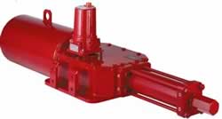
Figure 4: Hydraulic spring return fluid power actuator
- Fluid Power multi-turn actuators –These types of actuators are frequently
used when multi-turn output is required to operate a linear type valve such as
a gate or globe valve. Frequently electric actuators are used for this type of
valve. However, if there is no electric power supply readily available, then
pneumatic or hydraulic motors can be used to operate multi-turn actuators.
Selection criteria
:When selecting a valve actuator the correct type and size can be found
utilizing the following selection criteria:
- Power source –The common sources of power for automated valves are
electricity or fluid power. If electric power is selected, a three-phase
supply is usually required for large valves; however, small valves can be
operated on a single-phase supply. Usually an electric valve actuator can
accommodate any of the common voltages. Sometimes a DC supply is available.
This is often an emergency back-up power supply.
Variations of fluid power are much greater. First there is a variety of fluid
media such as compressed air, nitrogen, hydraulic fluid or natural gas. Then,
there are the variations in the available pressures of those media. With a
variety of cylinder sizes, most of the variations can be accommodated for a
particular valve size.
- The type of valve –Whenever sizing an actuator for a valve, the type of
valve has to be known, so that the correct type of actuator can be selected.
There are some valves that need multi-turn input, where as others need
quarter-turn. This has a great impact on the type of actuator that is
required. When combined with the available power supply, then the size and
type of actuator quickly comes into focus.
Generally multi-turn fluid power actuators are more expensive than multi-turn
electric actuators. However, for rising non-rotating stem valves a linear
fluid power actuator may be less expensive. A definitive selection cannot be
made until the power requirements of the valve are determined. After that
decision has been made, then the torque requirement of the valve is the next
selection criterion.
- Calculating the torque required by the valve –For a quarter-turn valve,
the best way of determining the torque required is by obtaining the valve
maker’s torque data. Most valve makers have measured the torque required to
operate their valves over the range of operating line pressures. They make
this information available for customers.
The situation is different for multi-turn valves. These can be subdivided into
several groups: the rising rotating, rising non-rotating, and non-rising
rotating valves. In each of these cases the measurement of the stem diameter
together with the lead and pitch of the valve stem thread is required in order
to size the automation for the valve. This information coupled with the size
of the valve and the differential pressure across the valve can be used to
calculate torque demand.
The type and size of the actuator can be determined after the power supply,
the type of valve, and the torque demand of that valve have been defined.
- Sizing the actuator –Once the actuator type has been selected and the
torque requirement of the valve has been determined, then the actuator can be
sized using one of the actuator manufacturer’s sizing programs or tables. A
further consideration in sizing the actuator is the required speed of
operation of the valve. As speed has a direct relationship to the power
required from the actuator, more horsepower would be needed to operate a valve
at a faster speed.
Fluid power actuators can adjust speed of operation using fluid control
valves. However, electric motor operators of the three-phase type have a fixed
speed of operation. Smaller, quarter-turn actuators utilize DC motors, and may
have adjustable speed of operation.
Controls
The great advantage of having an automated valve is that it can be remotely
controlled. This means that operators can sit in a control room and control a
process without having to physically go to the valve and give it an open or
close command, the most basic type of control for an automated valve. The
ability to remotely control a valve is easily achieved by running a pair of
wires out to the actuator from the control room. Applying power across the wires
can energize a coil, initiating motion in an electric or fluid power actuator.
Positioning a valve in an intermediate position can be done using this type of
control. However, feedback would be needed to verify the actuator is at the
desired position. A more common method of positioning an actuator is to feed a
proportional signal to the actuator such as 4-20 mA, so that the actuator, using
a comparator device, can position itself in direct portion to the received
signal.
Modulating control
If an actuator is required to control a level, flow or pressure in a system,
then it may be required to move frequently. Modulating or positioning control
can be achieved using the same 4-20 milliamps signal. However, the signal would
change as frequently as the process required. If very high rates of modulation
are required then special modulating control valve actuators are needed that can
accommodate the frequent starts required for such duty.
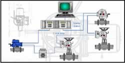
Figure 5: Digital communication systems
Where there are many actuators on a process, the capital cost of installation
can be reduced by utilizing digital communication over a communicating loop that
passes from one actuator to another. A digital communication loop can deliver
commands and collect actuator status rapidly and cost effectively. There are
many types of digital communication such as Foundation Fieldbus, Profibus,
DeviceNet, Hart, as well as proprietary communication systems custom designed
for valve actuator use such as Pakscan. Digital communication systems have many
advantages over and above the saving in capital cost. They are able to collect a
lot of data about the condition of the valve, and as such can be used for
predictive maintenance programs.
Predictive maintenance
Motor operators can utilize built-in data loggers coupled with highly accurate
torque sensing mechanisms to record data on the valve as it moves through its
stroke. The torque profiles can be used to monitor changes in the operating
conditions of the valve and to predict when maintenance is required. They can
also be used to trouble shoot valves.
Forces on a valve can include the following:
- Valve seal or packing friction
- Valve shaft, bearing friction
- Valve closure element seat friction
- Closure element in travel friction
- Hydro-dynamic forces on closure elements
- Stem piston effect
- Valve stem thread friction
Most of these are present in all types of valves, but in varying degrees of
magnitude. For example, closure element travel friction in a butterfly valve is
negligible. Where as a non-lubricated plug valve has significant in travel
friction. Valve actuators are designed to limit their torque to a preset level
using a torque switch, usually in a closing direction. An increase in torque
above this level will stop the actuator. In the opening direction, the torque
switch is frequently bypassed for the initial unseating operation. The resulting
torque profile is useful in analyzing the valve condition.
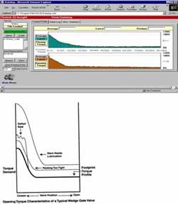
Figure 6: Gate valve torque profile
Different types of valves have different profiles. For example, a wedge gate
valve has significant torque at the opening and closing positions. During the
remaining portion of the stroke the torque demand is made up of packing and
thread friction on the acme threaded shaft. On seating, the hydrostatic force on
the closure element increases the seating friction, and finally the wedging
effect of the closure element in the seat causes a rapid increase in torque
demand until seating is completed. Changes in torque profile can therefore give
a good indication of pending problems and can provide valuable information for
an effective predictive valve maintenance program.
This article was originally published in the June 2004 issue of Valve World
magazine.